Guide to select of grinding wheels

This guide contains general principles for the selection of grinding wheels, applicable to all product categories. The individual product categories contain individual tips related to the needs of the specific product group.


Product category Product category designation
Resin bonded grinding wheels C01
Electroplated bonded grinding wheels C02
Vitrified and CBN bonded grinding wheels C03
Electrocorundum and silicon carbide vitrified bonded grinding wheels C04
Vitrified bonded grinding wheels for sharpening PCD/PCBN tools C05
Sintered metal bonded grinding wheels C06
Composite machining tools C07
Dressers C08

From a technological point of view, each grinding wheel consists of a bond and an abrasive . The type of bond determines the type of technology in which the abrasive disc was made, while the type of grit is dependent on the type of material being machined with the disc.

Selection of bond type

The selection of bond used determines the type of technology in which the grinding wheels are to be made. In contrast, its quantity in the abrasive mass influences the hardness of the grinding wheel, i.e. its ability to hold the grain. Hard wheels have a high grit holding capacity while soft wheels have a weaker grit holding capacity.

The table below shows the types of bonds used :

Bond Resin Polyimide Vitrified Galvanic Metallic
Symbol B P V G M

The above symbols from the table must appear when ordering a particular grinding wheel range. For examples of correct marking, see the sample orders for the individual ranges

Selection of abrasive grit type

The type of abrasive grit used is determined by the type of material that the wheel is intended to machine.

Type of grain Hardness Materials to be machined
CBN very high high-speed steel (HSS), tool steel, carburizing steel, bearing steel, stainless steel, and high-alloy steel with a hardness > 55HRC
Electrocorundum high carbon steels, alloyed steels C< 0.5%, cast steels, malleable cast irons, non-ferrous metals, stainless steels, nickel alloys, and chrome alloys
Diamond very high węgliki spiekane, szkło, ceramika, ferryt, krzem, grafit, tworzywa utwardzalne i wzmocnione włóknem szklanym, kamienie naturalne, materiały żaroodporne
Silicon carbide high high-speed steels, tool steels, sintered carbides, ceramics, hardened and grey cast irons, carbides, non-ferrous metals, plastics, leather and rubber

As a general rule of thumb, CBN is the superhard equivalent of electrocorundum and diamond of silicon carbide.

Principles of grinding wheel designation

Grinding wheels have a structured designation consisting of three parts:

Grinding wheel type Geometrical parameters Abrasive layer parameters
E.g. 1A1, 6A2, 9A3, 11V2, etc. Main dimensions of grinding wheels according to symbols used Hardness, type of grain, bond, structure if any, etc..

Marking the type of abrasive

The creation of the abrasive type follows strictly defined principles. The rules for creating the correct symbol of the grinding wheel are presented in the table below:
BODY SHAPE • ABRASIVE LAYER SHAPE • POSITION OF THE ABRASIVE LAYER

Body shape Abrasive layer shape Abrasive layer position
1
A
F
1
3
B
FF
2
4
BT
H
3
6
C
L
9
9
D
M
11
E
Q
12
EE
U
14
ET
V

Example: 14A1

This abrasive wheel has a body with the shape /14/, an abrasive layer with a rectangular cross-section /A/, positioned on the periphery of the body /1/

Example: 11V9

This abrasive wheel has a truncated cone-shaped body /11/ and an abrasive layer with a parallelogram cross-section /V/, positioned in its corner /9/.

Super-hard grain size

The grit size has a decisive influence on the grinding process, so its correct selection has a decisive impact on the results achieved.

The correct choice of grit size ensures that the wheel operates correctly and achieves the desired smoothness of the machined surfaces. In general, the smaller the grain size, the smoother the machined surface. However, the aim should not always be to achieve the smoothest possible surface, but always to achieve the desired results in the shortest possible time. This means that as coarse a grain as possible should be used which allows acceptable smoothness to be achieved.

Excessive allowances should not be used when grinding with fine grit grinding wheels, as this increases the wear of the abrasive layer and degrades the quality of the machined surfaces. For roughing, the coarsest possible grit should always be selected in order to maximise grinding efficiency.

It is recommended to use a grinding depth of no more than 1/3 of the nominal grain size stated in the grinding wheel characteristics. For example, for grit D126 according to FEPA, the grinding allowance should not exceed 0.042 mm.

The following criteria should be taken into account when selecting the grain size:
– type of machining (roughing, finishing)
– the desired smoothness of the workpiece surface
– expected grinding performance

FEPA grain symbol FEPA grain symbol FEPA, PN-85/M-59108 [µm] US Standard ASTM E11 [mesh]
D1181 B1181 1180/850 16/20
D852 B852 850/600 20/30
D602 B602 600/425 30/40
D427 B427 425/300 40/50
D301 B301 300/250 50/60
D251 B251 250/212 60/70
D213 B213 212/180 70/80
D181 B181 180/150 80/100
D151 B151 150/125 100/120
D126 B126 125/106 120/140
D107 B107 106/90 140/170
D91 B91 90/75 170/200
D76 B76 75/63 200/230
D64 B64 63/53 230/270
D54 B54 53/45 270/325
D46 B46 45/38 325/400

Grains below a granulation of 46 are called micropowders. The size table of these grains is as follows:

FEPA grain symbol FEPA grain symbol FEPA, PN-85/M-59108 [µm]
D30 B30 25/30
D20 B20 15/25
D15 B15 15/25
D9 B9 15/10
D7 B7 5/10
D3 B3 2/5
D1 B1 1/2
D0,7 B0,7 0,5/1
D0,25 B0,25 < 0,5

Super-hard grain concentration

Concentration determines the amount of diamond or boron grain per unit volume of the grinding wheel layer. The standard grain concentration values for resin bonded grinding wheels are shown in the table below.

Diamond Borazon
Concentration Grain content [carat/cm3] Concentration Grain content [carat/cm3]
K25 1,1 V60 1,05
K50 2,2 V120 2,09
K75 3,3 V180 3,13
K100 4,4 V240 4,18
K125 5,5 V300 5,22

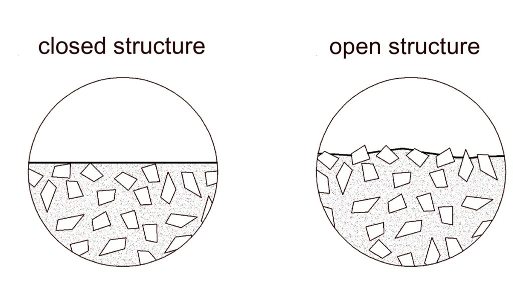
The concentration of abrasive grit in the working layer is one of the most important parameters of a grinding wheel. It affects the grinding wheel’s ability to grind, its service life, the temperature of the workpiece, and also the accuracy of the machining. Like any parameter, the concentration should be properly selected to suit the grinding process conditions. It should be remembered that the optimum concentration value depends on the other parameters of the grinding wheel, i.e. grit size, bond hardness, etc.

High concentration (K100, K125; V240, V300) is recommended for:
– high demands on the behaviour of the grinding wheel profile during operation
– low abrasive layer height
– hard bond
– coarse grain
– deep grinding

A standard concentration (K50, K75; V120, V180) is recommended for:
– grinding of planes and cylindrical surfaces
– medium abrasive layer height
– soft bond
– fine grain

A low concentration (K25; V60) is recommended for:
– very wide abrasive layers
– very fine grain

A high grain concentration increases tool life, which is particularly important for contour grinding and for grinding workpieces with very small diameters. The benefits of a high tool life generally offset the higher cost of the tool.

A disadvantage with high grain concentration is the occurrence of higher cutting forces and an increase in the temperature of the machining process. A high concentration of grain is not always the most favourable and technologically best solution, but it certainly requires good cooling.

Wheel body material selection

Body material
The grinding wheel body can be made from a variety of materials. The material of the body, through its vibration damping or heat dissipation properties, fundamentally influences the grinding process. Therefore, its selection should depend on the expected processing parameters.

The following materials are available:
– aluminium, resin tools, ceramics
– moulding compound, resin tools
– steel
– ceramics, ceramic tools

A comparison of the characteristics of the available materials is shown in the table below:

Body Material Symbol Vibration dampingigkeit Thermal conductivity Mechanical strength
aluminium KA weak very good good
ceramic KC medium good medium
composite KT medium satisfactory medium
steel KS weak good very good

Selection of disc diameter

The primary criterion for diameter selection is the type of grinder being used. If there is a choice, large diameter grinding wheels should be used. The advantage of this is the improved quality of the machined surface and the higher cost-effectiveness of the work due to the higher machining performance.

When grinding holes, make sure that the diameter of the grinding wheel is between 60 and 80% of the diameter of the hole being ground. Smaller-diameter grinding wheels prevent the achievement of a high quality machined surface, while larger wheels make it difficult to remove the spoil.

Criteria for selection of grinding wheel hardness

We define the hardness of a grinding wheel as the ability of the wheel to hold the grain. Hard wheels have a high grit holding capacity while soft wheels have a weaker grit holding capacity.

The selection of wheel hardness depends on a number of grinding wheel operating parameters. Commonly used selection criteria are presented in the table below:

Machinging parameters Soft Hard
Grinding width large small
Grain size fine coarse
Working conditions dry wet
Workpiece
hardness
higher lower
Other criteria high heat sensitivity of the workpiece high requirements regarding manufacturing tolerances

Characteristics of CBN

Cubic boron nitride (CBN) is produced similarly to synthetic diamond. CBN is the second hardest artificially produced abrasive. Unlike diamond, it is not adversely affected by iron, making it ideal for machining all types of alloy steels.

CBN tools have a higher wear resistance compared to conventional tools, and it is easier to achieve the desired dimensions and surface quality of workpieces using them. The aforementioned features make it possible to achieve significantly higher productivity and lower costs in the grinding process when using CBN tools.

Characteristics of diamond

Diamond has the highest hardness of any abrasive known to man. Its hardness and wear resistance, as well as its high thermal resistance, make it particularly suitable for use in grinding difficult-to-machine materials.

Today, 90% of industrial diamond is produced synthetically from graphite. Under high pressure and temperature in the presence of catalysts, the crystallographic lattice of graphite is transformed, resulting in synthetic diamond. As a result of this controlled process, diamonds with different properties can be obtained, enabling the precise selection of the type of abrasive grain to meet the customer’s requirements.

Characteristics of electrocorundum

Electrocorundum is a synthetic abrasive consisting of a crystalline aluminium oxide (α-Al2O3) called alumina and a small amount of additives. Depending on the content of foreign oxides of TiO2, Si02, Fe2O3, CaO, MgO or NaO2, the following types of electrocorundum are distinguished:

Name Colour Al2O3 content Materials to be processed
Ordinary electrocorundum 95A grey-blue or brown approx. 94.5% carbon steel C< 0.5%; cast steels, malleable cast irons, non-ferrous metals
Semi-precious aluminium oxide 97A grey-brown or grey-blue approx 97,5% carbon steels and alloy steels with a C content of 0.5% and a hardness of up to 60HRC
carbon steels and alloy steels with a C content of 0.5% and a hardness of up to 60HRC white over 98% carbon and alloy steels with a content of C>0.5% and a hardness of more than 62HRC
Monocrystalline electrocorundum 32A pale pink over 98% carbon and alloy steels with a content of C>0.5% and a hardness of more than 62HRC
Microcrystalline alumina Cubitron SG blue approx. 95% stainless steels, titanium, chromium and nickel alloys
Elektrokorund mikrokrystaliczny Cerpass XTL white approx. 99,6% Cerpass XTL microcrystal electrocorundum

In addition to the aforementioned types of alumina, several special grades are produced by smelting, such as chrome alumina (pink in colour), zirconia, titanium and others.

Silicon carbide characteristics

In addition to electrocorundum, silicon carbide is a commonly used abrasive. Silicon carbide comes in two varieties:

Types of silicon carbide

Name Colour SiC content Materials to be machined
Silicon carbide green 99C dark green 99,66% high speed steels, tool steels, carbides, ceramics
Silicon carbide black 98C black 98,26% hardened and grey cast irons, sintered carbides, non-ferrous metals, plastics, leather and rubber

In terms of chemical composition and physical properties, the two silicon carbide varieties differ slightly; however, green silicon carbide contains fewer additives, making it more brittle and giving it better abrasive properties.

Selection of abrasive layer width 'W'

General recommendations indicate the need to use the smallest W layer widths as possible. The width of the grinding wheel working layer must always be smaller than the workpiece width. If this is not the case, a fault is created on the working surface of the grinding wheel contributing to increased wear:

The height of the tool’s abrasive layer does not fundamentally affect the grinding process, but only the price of the tool itself. Taking into account the economic aspect, it is advantageous to use a higher X layer if the processing conditions allow it.


Cooling during machining

Cooling during machining
The wet grinding process (with cooling) is superior to the dry grinding process (without cooling) in terms of both wheel life and cutting performance. Cooling contributes to improved grinding conditions by improving spoil removal and lowering the temperature in the grinding zone. Therefore, wet sanding should be used wherever possible. Several per cent oil-water emulsions or mineral oils with some additives to increase cooling efficiency are used as coolants.


Grinding speed, peripheral

During grinding operations, the grinding speed, which is the linear velocity of the grains on the surface of the abrasive layer, plays a very important role. The correct selection of this speed, depending on the workpiece material and type of machining, is a fundamental issue when grinding.

Recommended grinding speeds for bond types ‘B’, ‘P’, ‘M’, ‘G’ depending on the grinding conditions are given in the table below:

Type of grain Dry Wet
Diamond 15 ÷ 20 m/s 20 ÷ 40 m/s
CBN 15 ÷ 30 m/s 25 ÷ 50 m/s

Note, for ‘V’ type vitrified bonds made on ‘KC’ ceramic bodies, grinding speeds of 35 m/s should not be exceeded. For grinding speeds above 35 m/s, use ‘KA’ type aluminium wheel bodies.

Speed

The speed, denoted as ‘n’, indicates the number of revolutions/minute of the abrasive tool, i.e. how many revolutions the abrasive tool makes in one minute. Grinding speed, designated ‘Vc’, is the speed at which a single abrasive grain cuts the workpiece.The two speeds correspond to each other according to the following formula:

π – ~3,14
d [mm]- disc diameter
n [rpm ⁄ min] – machine spindle speed with abrasive tool

For diamond or CBN, the peripheral velocity ‘Vc’ should be in the range: 20/30 [m/s]

Example – speed calculation [rpm]
for an abrasive tool diameter d = 22 mm, assuming that the disc grinds with the peripheral

Grinding peformance

The grinding wheel performance can be defined as the ratio of volume of material removed in a particular grinding operation to the used volume of the abrasive layer of the grinding wheel:

G = VuVz

where:
G, grinding performance factor
Vu , volume of material removed [mm ]
Vz , used volume of the abrasive layer of the grinding wheel [mm ]

A higher ratio of these values means higher performance of a particular grinding wheel, resulting in a reduction in unit costs of the product in question.

Opening the grinding wheel structure

In a properly used grinding wheel, the grain ‘protrudes’ above the surface of the bond, allowing it to work properly. If the working surface is ‘stuck’, the efficiency of grinding decreases dramatically. In this case, the structure of the grinding wheel should be ‘opened up’ with a ceramic whetstone. The essence of the operation is presented in the figure:

Wheel balancing

At the end of the production process, grinding wheels are dynamically balanced to ensure:
– optimum wheel life
– minimal wear on the grinder bearings
– the desired machining accuracy

When working with an unbalanced grinding wheel, there is partial contact between the abrasive layer and the workpiece. This causes wear of the grinding wheel in a short period of time at a particular location, which exacerbates the unbalance and increases the roughness of the machined surface.

A balanced grinding wheel is considered to be one whose centre of gravity coincides with the geometric centre of the disc’s axis of rotation.

Solving grinding problems

If the grinding results do not produce the desired results, it is important to ensure that the process parameters have been chosen correctly. If so, and the problems persist, the cause should be determined.

A list of the most common problems encountered during hole machining and possible ways of eliminating them is presented in the table:

Problem Possible causes
The grinding wheel does not grind, overheating of the workpiece surface occurs. 1. Bond too hard or inappropriate
2. Peripheral speed too high
3. Insufficient cooling
4. Feed rate too fast
5. Excessively large contact area of the grinding wheel workpiece
6. Concentration too high
7. Grain too fine
8. Grinding wheel not balanced
Rapid wear of the grinding wheel, rapid loss of working profile. 1. Bond too soft or inappropriate
2. Insufficient cooling
3. Concentration too low
4. Peripheral speed too low
5. Grain too coarse
6. Feed rate too fast or too much allowance
7. Grinding wheel not balanced
Excessive roughness of machined surface 1. Grain too coarse
2. Peripheral speed too low
3. Bond too soft
4. Contaminated coolant
5. Inadequate sparking
6. Feed rate too fast
7. Grinding wheel is “stuck”

The probable causes listed next are not the only ones that can cause certain abnormalities, the reasons listed are simply the most common ones.

Troubleshooting different types of machining

Problem Shaft grinding Wheelless grinding Hole grinding Surface grinding Tool sharpening
Burns, cracks


1. Grinding wheel too hard
2. Incorrectly dressed grinding wheel
3. Plunge feed too high
4. Object speed too slow
1. Grinding wheel too hard
2. Incorrectly dressed grinding wheel
3. Plunge feed too high
4. Object speed too slow
1. Grinding wheel too hard
2. Incorrectly dressed grinding wheel
3. Plunge feed too high
4. Object speed too low
5. Contaminated coolant
1. Grinding wheel too hard
2. Incorrectly dressed grinding wheel
3. Plunge feed too high
4. Object speed too slow
1. Grinding wheel too hard
2. Plunge feed too high
3. Contaminated coolant
Comma marks, scratches, tears 1. Grinding wheel too soft
2. Grain too coarse
3. Unbalanced grinding wheel
4. Incorrectly dressed grinding wheel
5. Feed-in too great
6. Object speed too slow
7. Contaminated coolant
1.Contaminated coolant
2. Dirty support
1. Grinding wheel too soft
2. Incorrectly dressed grinding wheel
3.Contaminated coolant
4. Spindle clearance
1. Incorrectly dressed grinding wheel
2.Contaminated coolant
1. Grinding wheel too soft
2. Grain too coarse
3. Contaminated coolant
Blunting and sticking of the grinding wheel 1. Grinding wheel too hard 2. Grain too fine 3. Feed rate too low 4. Insufficient plunge feed 5. Insuffiecient coolant. 1. Grinding wheel too hard
2. Grain too fine
3. Feed rate too low
4. Insufficient plunge feed
5. Insufficient coolant
1. Grinding wheel too hard
2. Grain too fine
3. Insufficient coolant
1. Grinding wheel too hard
2. Grain too fine
3. Feed rate too low
4. Insufficient coolant
1. Grinding wheel too hard
2. Grain too fine
Deviations in the shape of the object 1. Grinding wheel too soft
2. Incorrectly dressed grinding wheel
3. Plunge feed too high
4. Uneven runout of the grinding wheel
5. Misalignment of machine tool components
1. Grinding wheel too hard
2. Incorrectly dressed grinding wheel
3. Plunge feed too high
4. Incorrect angle of the support
5. Grinding too high over the axis
6. Incorrect guides
7. Defective guide disc
1. Grinding wheel too hard
2. Grain too fine
3. Feed rate too low
4. Insufficient coolant
5. Uneven runout of the grinding wheel
6. Misalignment of machine tool components
1. Grinding wheel too soft
2. Grinding speed too low
3. Uneven runout of the grinding wheel
1.Grinding wheel too soft
2. Spindle clearance
3.Machine tool vibrations


Troubleshooting problems with the quality of the machined surface


Problem Possible causes Solution
Excessive roughness of machined surface 1. Spindle speed too low
2. Plunge feed too high
3. Too little allowance – traces left over from previous processing
4. Grain size too large
5. Inappropriate coolant
6. Insufficient coolant
1. Increase in speed
2. Reduce feed rate
3. Increase allowance
4. Reduce grain size
5. Change coolant
6. Increase flow and/or pressure.

 Converging cone


1. Activation of the spindle rotation when the grinding wheel is too high
2. Too much clamping force on the object causing deformation
3. Grinding speed too slow
4. Spindle or grinder chuck run-out
5. Spindle speed too high
6. Spindle speed does not reduce when withdrawing the grinding wheel
7. Too slow withdrawal of the grinding wheel
8. Large inaccuracy created during previous processing
9. Grinding wheel grinds too aggressively
10. Feed rate too low.
1. Change position of the grinding wheel
2. Reduce clamping force – stresses must be minimal and uniform
3. Increase grinding speed
4. Eliminate run-out
5. Reduce spindle speed
6. Reduce spindle speed
7. Increase speed
8. Re-grind
9. Reduce grain size
10. Increase feed

Converging cone

1. Position of the feed diversion point too deep
2. Machining of the lower part of the workpiece too long
3. Grinding wheel grinds too aggressively
4. Non-perpendicular attachment of the object
5. Too much clamping force on the object causing deformation
6. Spindle speed too high
7. Spindle or grinder chuck run-out
8. Large inaccuracy created during previous processing
1. Correctly position point
2. Immediately withdraw the grinding wheel
3. Reduce grain size
4. Correctly position the object
5. Reduce clamping force – stresses must be minimal and uniform
6. Reduce spindle speed
7. Elimination of run-out
8. Re-grinding

Hourglass

1. Grinding wheel grinds too aggressively
2. The wheel operates at an angle
3. The object is not fixed centrally and perpendicularly
4. Spindle speed too high
5. Too much clamping force on the object causing deformation
6. Large inaccuracy created during previous processing
7. Deformation of an object due to heat treatment
8. Feed rate too low
1. Reduce grain size
2. Correctly position the object
3. Correctly mount the object
4. Reduce spindle speed
5. Reduced clamping force – stresses must be minimal and uniform
6. Re-grind
7. Re-grind
8. Increase feed

Barrel

1. Too much clamping force on the object causing deformation in the central part
2. The object has thin walls at the top and bottom causing its deformation during machining
3. Insufficient feed
4. Excessive spindle speed
1. Reduce clamping force – stresses must be minimal and uniform
2. Reduce allowance
3. Increase feed
4. Reduce spindle speed

Oval at the top

1. Activation of the spindle rotation when the grinding wheel is too high
2. Spindle speed too high
3. Grinding wheel grinds too aggressively
4. Spindle or grinder chuck run-out
5. Spindle speed does not reduce when withdrawing the grinding wheel
6. Too much clamping force on the object causing deformation
7. Insufficient feed
1. Change position of the grinding wheel
2. Reduce spindle speed
3. Reduce grain size
4. Contaminated coolant
5. Reduce spindle speed
6. Reduce clamping force – stresses must be minimal and uniform
7. Increase feed

Oval at the bottom

1. Position of the feed diversion point too deep
2. Machining of the lower part of the workpiece too long
3. Grinding wheel grinds too aggressively
4. Spindle speed too high
5. Too much clamping force on the object causing deformation
6. Insufficient feed
1. Correctly position the point
2. Immediately withdraw the grinding wheel
3. Reduce grain size
4. Reduce spindle speed
5. Reduce clamping force – stresses must be minimal and uniform
6. Increase feed


Ordering

The grinding wheel selection scheme is as follows:
geometrical parameters such as:
– type of wheel, dimensions of the abrasive layer and diameter of the bore or shank
– depending on the material to be machined and the processing, the type, concentration and size of the grit and hardness of the bond should be selected
– specify operating conditions with cooling (wet) or without cooling (dry)

If possible, please specify in your order the type of material and machining, as well as its conditions and the type of machine for which the grinding wheels are to be used. This will allow us to adapt the wheel as closely as possible to your needs and reduce selection time.

If the grinding wheel you are interested in is not available on our website, we can manufacture it to your special order. This page contains examples of the most popular products in our range.

HAVE QUESTIONS?

Contact us

INTER-DIAMENT® Kacprzycki Sp.j.
st. Chełmońskiego 30
05-825 Grodzisk Mazowiecki, Poland